What is manganese blow bars?
Crusher blow bars are the main wear parts for impact crusher. The blow bars are manufactured by manganese steel and manganese alloy steel, which are called manganese blow bars.
This manganese steel is used in primary crushers or crushers that have tramp iron in the feed. Manganese steels will be used whenever very high shock resistance or some elongation is needed. The blow bar life is not easily predictable and depends on many factors. Manganese crusher blow bars are commonly used primary crusher applications and provide high shock resistance and are available in both Mn14% and Mn18% material grades. They are well suited to applications where tramp iron is possible in the feed material. Manganese bars are often used as a ‘safe’ choice, however, other materials available can offer significant life costs benefits. For identification purposes, manganese steel blow bars are painted black or red and marked with the respective material grade. Also, ask about our special high-performance material that is proven to outperform other grades of manganese blow bars.
Manganese blow bars chemical composition
Regularly, manganese blow bars are manufactured by GB/T 5680-2010 Standard in China, which include Mn14, Mn14Cr2, Mn18, M18Cr2, Mn22, Mn22Cr2, and manganese alloy steel. Its detailed chemical composition is shown in the following tab.
| Grade | Manganese Blow Bars Chemical Composition % | ||||||||
| C | Si | Mn | P | S | Cr | Mo | Ni | W | |
| ZG120Mn7Mo1 | 1.05-1.35 | 0.3-0.9 | 6-8 | ≤0.060 | ≤0.040 | – | 0.9-1.2 | – | – |
| ZG110Mn13Mo1 | 0.75-1.35 | 0.3-0.9 | 11-14 | ≤0.060 | ≤0.040 | – | 0.9-1.2 | – | – |
| ZG100Mn13 | 0.90-1.05 | 0.3-0.9 | 11-14 | ≤0.060 | ≤0.040 | – | – | – | – |
| ZG120Mn13 | 1.05-1.35 | 0.3-0.9 | 11-14 | ≤0.060 | ≤0.040 | – | – | – | – |
| ZG120Mn13Cr2 | 1.05-1.35 | 0.3-0.9 | 11-14 | ≤0.060 | ≤0.040 | 1.5-2.5 | – | – | – |
| ZG120Mn13W1 | 1.05-1.35 | 0.3-0.9 | 11-14 | ≤0.060 | ≤0.040 | – | – | – | 0.9-1.2 |
| ZG120Mn13Ni3 | 1.05-1.35 | 0.3-0.9 | 11-14 | ≤0.060 | ≤0.040 | – | – | 3-4 | – |
| ZG90Mn14Mo1 | 0.70-1.00 | 0.3-0.6 | 13-15 | ≤0.070 | ≤0.040 | – | 1.0-1.8 | – | – |
| ZG120Mn17 | 1.05-1.35 | 0.3-0.9 | 16-19 | ≤0.060 | ≤0.040 | – | – | – | – |
| ZG120Mn17Cr2 | 1.05-1.35 | 0.3-0.9 | 16-19 | ≤0.060 | ≤0.040 | 1.5-2.5 | – | – | – |
| Notice: Accept join the element V,Ti,Nb,B,Re | |||||||||
Manganese blow bars foundry
Qiming Machinery is one of the largest manganese steel foundries in China. Our feature products covered manganese blow bars. Qiming Machinery leads the way in quality and support–beyond what you’d experience with conventional impact crusher wear parts. Qiming Machinery delivers premium replacement parts for your next impact crusher repair. In most cases, we have the part on the shelf and ready for immediate shipment. In some cases, Qiming Machinery has even improved the conventional design of the part to enhance durability and performance. Compare with other foundries, Qiming Machinery has the following advantages:
- Quality Advantage. All of our parts are backed by ISO9001:2015 quality control system;
- Professional Advantage. We have a professional engineers team wait for your questions;
- After-sales Service Advantage. All of our wear parts have 3 years traceability period.
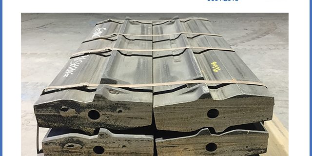
Study Case-840kg manganese blow bars manufacture
The structure of the high manganese steel in-service state is austenite. Because of its good toughness and work hardening ability, it is widely used in mine impact resistant parts. One of our customers, who use heavy manganese blow bars from Germany foundry. Its weight 840kg, size: 2000mm*394mm*158mm, effective thickness 140 mm, 4 pieces per set, crush capacity: 700 tons per set.
Due to the large impact load and high speed of the crusher, the crusher blow bars must have good toughness and wear resistance. The original use of high manganese steel blow bars produced by many manufacturers, there are either some fractures, or some are not wear-resistant, including the imported blow bars also has the problem of using interruption crack.
Based on the working conditions, Qiming Machinery starts to manufacture these manganese steel blow bars.
Design of chemical composition
Based on the working conditions, we choose the following material to cast these blow bars:
- 0. 90 %~1. 20 % C ,
- 0. 5 %~0. 8 % Si ,
- 12 %~ 14 % Mn ,
- 1. 0 % ~2. 0 % Cr ,
- 0. 2 % ~0. 6 % Mo ,
- 0. 15 %~0. 25 % V ,
- 0. 05 %~0. 12 % Ti ,
- ≤0. 06 % P ,
- ≤0. 03 % S.
Heat Treatment
Selection of water toughening medium
In the heat treatment of high manganese steel, undercooled austenite is obtained by rapidly cooling the structure after heating and holding, that is, the high-temperature austenite is retained to room temperature.
When the heated workpiece is cooled in still water, a vapor film is formed on the working surface at about 800-400 ℃, and the heat transfer is relatively slow; when it is cooled to about 300 ℃, the steam film breaks and enters the boiling cooling stage, and the cooling rate increases sharply; when it is cooled to below 100 ℃, the boiling disappears and enters the convection cooling stage, and the cooling speed is relatively slow. Sodium chloride can reduce the stability of steam film, promote the rupture of steam film, increase the characteristic temperature, move the maximum cooling rate to 500 ℃, enhance the cooling capacity and increase the cooling rate. Therefore, choosing 2% ~ 5% sodium chloride solution as a cooling medium for water toughening treatment is more conducive to ensure the quality of water toughening treatment for large high manganese steel.
Heat treatment process
Due to the poor thermal conductivity of high manganese steel castings and the thickness of the castings (158 mm), the heating rate below 650 ℃ should be strictly controlled and set as 0.5 ℃ / min. In order to prevent cracks in the heating process, heat preservation was conducted at 650 ℃ for 3 h and raised to 1 060 ℃ for 6 h. water toughening treatment was carried out by rapidly adding water into the furnace. The temperature of the medium should be kept below 40 ℃ for 2 min.
Mechanical properties and microstructure after heat treatment
Due to the large size of the casting, it is impossible to take the body sample for the performance test after heat treatment. Therefore, the test block with the contour size of 170 mm × 170 mm × 150 mm is attached during the production of the casting, which is treated in the same heat treatment furnace along with the casting. After heat treatment, a 10 mm × 10 mm × 55 mm u-notch impact specimen was cut from the test block by EDM numerical control wire cutting machine. The impact property was tested on the JB-30B impact testing machine and the microstructure was observed on the XJL-203 vertical metallographic microscope. The test results are as follows: the impact toughness αKu is 160 ~ 205 J / cm2, the hardness is 210 ~ 220 Hb, and the microstructure is austenite, which is completely qualified.
Casting process design
Using sodium silicate sand molding, the linear shrinkage rate is 2.7% ~ 3.0%. Considering the working conditions, it is necessary to ensure that the castings are compact and the process yield is about 60%. Three top risers are used, and the section ratio of the gating system is within ∑ F:∑ f horizontal ∶ f direct = 1 ∶ 0.85 ∶ 1.2.
Because the casting is thick, in order to avoid the use of direct external cooling iron.
If there are cracks or defects of cold iron fusion welding on the casting, the “sand proof external cold iron” with sand separation of 10-15 mm is used. The outer chill thickness t = (0.8-1.1) δ (casting thickness) and chill length L = (2.0-2.5) t. The distance between the outer chill should be 20-25 mm, and the vertical and horizontal gaps should be staggered to avoid the formation of regular cooling weak surface and the casting cracks between the chills.
In order to make the chilling capacity of cold iron gradually transition, the periphery of external cold iron is made into a 45 ℃ inclined plane.
According to the above process, the castings have passed cts222a ultrasonic inspection, and there are no internal defects.
Cooling process after pouring
The cast iron must be removed in time after pouring and the casting box must be removed to reduce the casting shrinkage resistance. In general, the temperature of simple thin-walled castings should be lower than 400 ℃, while that of complex heavy castings should be lower than 200 ℃. For castings of general complexity, the ex box time can refer to the empirical formula of the former Soviet Union’s Nochke factory
τ = (2. 5 + 0. 075δ) K
Where τ is the time from pouring to discharging, h; δ is the representative wall thickness of casting, mm;
K — coefficient related to pouring temperature (T).
When t ≤ 1 400 ℃, k = 1.00; when t = 1 400 ~ 1 450 ℃
When t = 1 455 ~ 1 460 ℃, k = 1.15; when t > 1 465 ℃, k = 1.25 [4]. According to the thickness of the casting and the production characteristics of our company, the pouring temperature is 1 430 ~ 1 460 ℃, considering the heavy casting, it is determined that the temperature out of the box is lower than 200 ℃, and the time from pouring to discharging should be more than 20 h.